

As I’ve worked through a growing number of Fender project builds – I’ve standardised many of the common processes I encounter along the way. Normally – certain issues – quite often to do withthings like the availability of parts… doing things in, not necessarily, the most logical order… not getting the correct parts to fit in the first place, etc. etc. – can combine to make the process quite an unnecessarily lengthy and circuitous exercise – with many possible rabbit holes to get lost down, on the way. However – it really doesn’t have to be like that. It’s quite possible to make the whole assembly process something of a “weekend venture” – if you know what you’re doing, and plan ahead.
Of course – the basic sequence of processes differs slightly for different Fender “models” – Stratocaster, Telecaster, Jaguar etc.. Each have their own particular challenges – but in terms of difficulty level – I suppose the Esquire/Telecaster is a little bit easier to begin with, than some of the others. So – with this particular “Strummer” Fender Esquire build – I’ll try to run through the components and main procedures – laid out in a (hopefully) logical and expeditious way. That should keep the number of posts down to a more informative level – and provide a bit more of a reliable, “step-by-step” methodology, for any who may wish to follow. The procedure will aim to produce a fully shielded guitar, with a central “star” grounding point for the tone circuit. I’ll be using predominantly all-Fender components, which should guarantee compatibility throughout. (Many of the “occasional problems” encountered, whenever building “kit” guitars, often have their roots in component “mismatches”. If you’re considering using generic or substitute parts at all – always check dimensions carefully, and ensure substitutes are specifically designed to conform with standard Fender specifications).
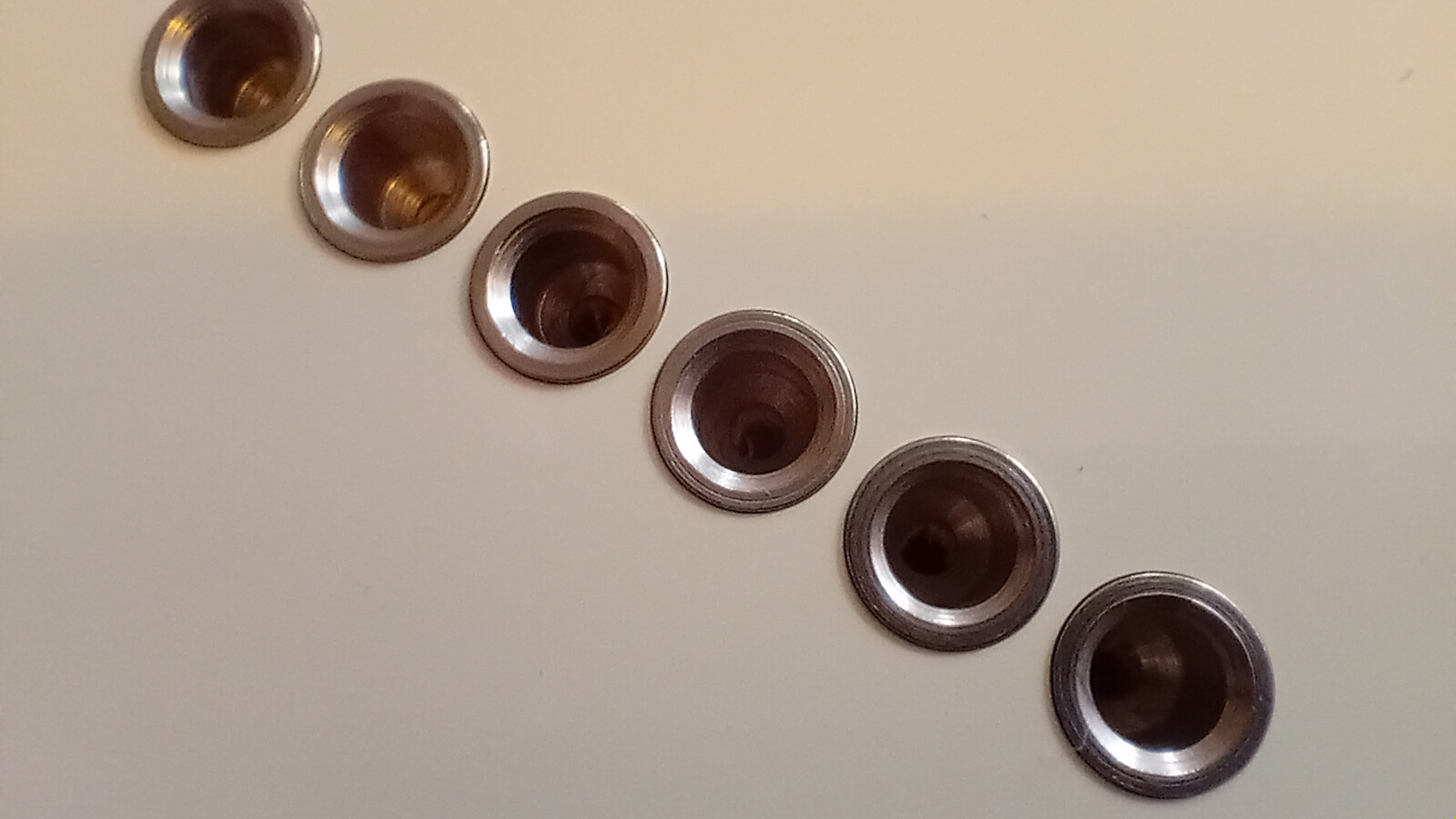
First off – with Telecasters – the through-body stringing requires a set of six string ferrules to be installed onto the back of the guitar. This – being a brand new Fender “Classic 60’s” MIM Telecaster body – (Fender parts code: 099-8006-705) – it comes already accurately routed to accept a set of push-in, vintage style, Fender ferrules (Fender parts code: 099-4918-000). The ferrules fit incredibly snugly, and it can sometimes look as if the pre-drilled holes aren’t quite large enough. However – line them up correctly, press them home straight and true – and the ferrules will push home so that they’re set, semi-recessed, into the body, with no damage to the surrounding paintwork. To help push the ferrules home – I use a suitably sized, cross-head screwdriver – and simply push them home firmly. There’s no need to glue them in, or anything… Friction is usually enough – and once the strings are installed – they’ll be even further secured into the body.
(Of course – a proper fit requires the correct type of ferrules to begin with – in order to fit the exact tolerances of any pre-drilled holes. If you work with either a non-Fender body, or ferrules – all bets are off, and you may have to do some additional prep work to get everything to fit correctly. Additionally – bear in mind that Fender “Vintage” models can sometimes require slightly differently tooled components, to those designed specifically for more “Modern” designs. It’s something that you get used to with experience – but getting hold of a full specification breakdown for a particular “target” build, will usually help to identify and track down any particular parts you‘ll need. Sometimes, you may have to buy stuff in from Fender distributors and authorised resellers in the USA, or Europe. If you choose to use generic, non-Fender “upgrades” – for whatever reason – prepare to accept the inevitability of, at least, a few mis-alignments, or differences in tolerance. If you begin to run into this sort of thing regularly – it’s usually worth investing in a few specialist tools, to help carry out any additional prep work, and to get things to fit together properly).
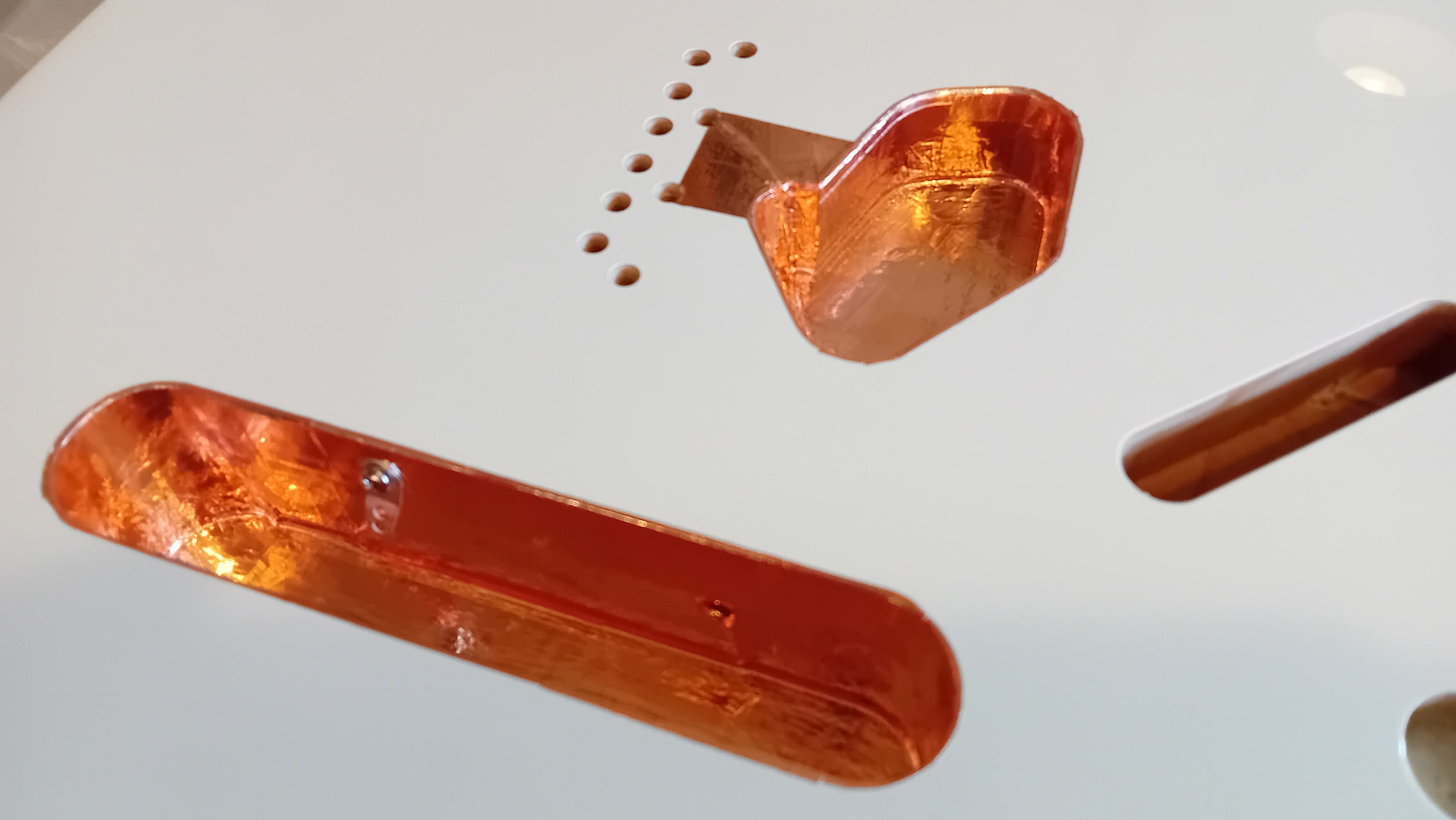
With the ferrules in place on the back of the guitar – I can then turn the body over and start to work on the shielding. This is also the best time to lay any grounding wires, which will link outlying cavities and components back to a central grounding point in the main control cavity. Shielding involves lining all of the main body routs with self-adhesive backed, heavy gauge, copper foil. The adhesive on the foil I use is strong and conductive – and so overlapping many separate strips of the foil gradually builds-up a durable and continuous lining throughout. This will eventually form the body-side half of an enveloping “Farraday Cage” – which will shield internal electrical wires and components from outside electro-magnetic interference. (60Hz cycle hum, SW radio interference, etc.). I usually try to restrict coverage to within the cutouts – with just a millimetre or so rolling out, over the lip, and onto the face of the body. (It looks much tidier, and doesn’t waste so much unnescessary foil). Once the various cover plates and other metal components are in place – they will complete the shielding “cage” effect, over the top.
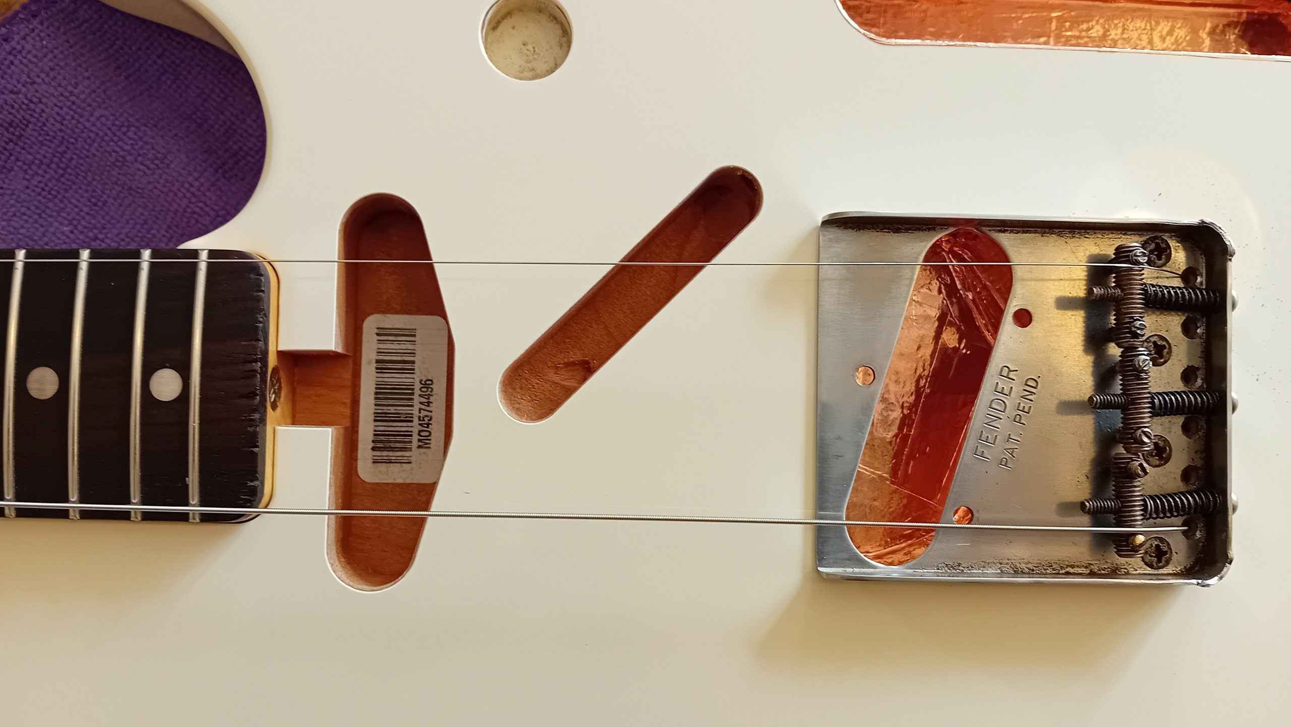
The foil is laid piece by piece, and then burnished down with an agate, “dog tooth” polishing tool – (a handy addition to the toolbox, pinched from a gold-leafing toolset). The nature of the adhesive foil means it’s also useful to help secure any interconnecting wires required – between conduits – where the foil can be used both to hold wires in place, and to reinforce the required conductive connection. For this particular “Esquire” type build – only the bridge pickup and main control conduits need to be shielded, and a single connecting wire can be laid between the two. (With the second neck pickup on a full “Telecaster” fitout – the neck pickup rout and the diagonal cable rout also need to be shielded – with connecting groundwires laid so that all of the separate cavities end up effectively linked).
In this case – to keep things neat – the same connecting wire laid between the bridge and main cavities can be extended, and used to directly ground the metal bridge plate back to the main “star” grounding point. To create a solid contact point under the bridge plate – I usually lay a little extra tab of copper to run over the lip of the bridge pickup cutout – and run that back towards the middle two of the four main bridge screwholes. The wire can run over this “pad” and can be sandwiched, with another piece of foil over the top. The downward pressure of the bridge will then permanently maintain the ground connection.
Using the stripped core of some spare push-back wire – I lay a running ground – starting down in one of the bridge screwholes… across the newly laid copper tab on the face of the body… over the lip and down into the pickup cavity… tight aroud the base of the cavity and around to the drilled conduit… and through into the main control cavity. Leave plenty of spare wire there to run on. Small strips of foil can be used to hold the wire in place as it’s laid – and as additional foil begins to be built up around the insides – the running wire can be pushed into shape around the bottom angles of the conduits as the foil is burnished down on top.
Within the main control cavity – the wire is directed along the bottom edge, and up to a newly located screw lug – which is carefully positioned so that it will lie in-between the positions of the two control pots on the main control plate. The screw lug is set into the side wall, with the free end of the running wire pushed into the lug hole – so that the wire is eventually secured in position, both by a covering of copper shielding foil, and the lug screw – as it’s driven home. Eventually – the tab of the lug will allow other circuit wires to be directly connected-back to this single, central point. A “star” ground is a good way to keep the on-body internal wiring tidy and logical. Once the shielding has been completed – conductivity can be checked and confirmed with a multimeter set to “continuity” mode.
Now – I can begin to mount some of the other on-body components. Starting, (probably most importantly), with the bridge. However – to help ensure that the bridge is mounted straight, and in-line with the neck – I’ll first need to mount the neck which needs to have tuners and a roughly-slotted nut already fitted. Practically-speaking – this does, sometimes, provide one of those sequential “procurement problems” I talked about earlier. So – in order to keep things constantly moving along – I’ve collected a small selection of spare, “dependable” substitutes. These – (one each for different sorts of fittings, scale lengths etc. – Strat, Tele, Jag, Jazz etc.) – might not necessarily be genuine Fender necks – but they all conform to basic Fender specifications. (I know they’ve worked for me before, and I know they’re straight. These probably got sustituted out as I upgraded, and now tend to move from build to build as “placeholders” – standing-in until I find the ideal neck I’m looking for, for each particular build). For this Strummer Esquire – I really want a Fender neck with a rosewood fingerboard – but until I can find a second-hand one somewhere, or unless I compromise with a new Pau Ferro board, or even just opt for a suitably-finished non-Fender alternative – I’ll have to stick with one of my “substitutes” in the meanwhile.
So – I’m using a Hosco Tele neck here, (vintage style). This one has recently been reliced for use on my, (now stalled), 60’s “Slab board” Tele relic – but has also been re-appropriated at different times, for other jobs along the way. It’ll work reasonably well here until I can find just the thing I’m looking for – and meanwhile – I know it’s Fender licensed, and is accurate enough to locate all of the other components, in place, around it.
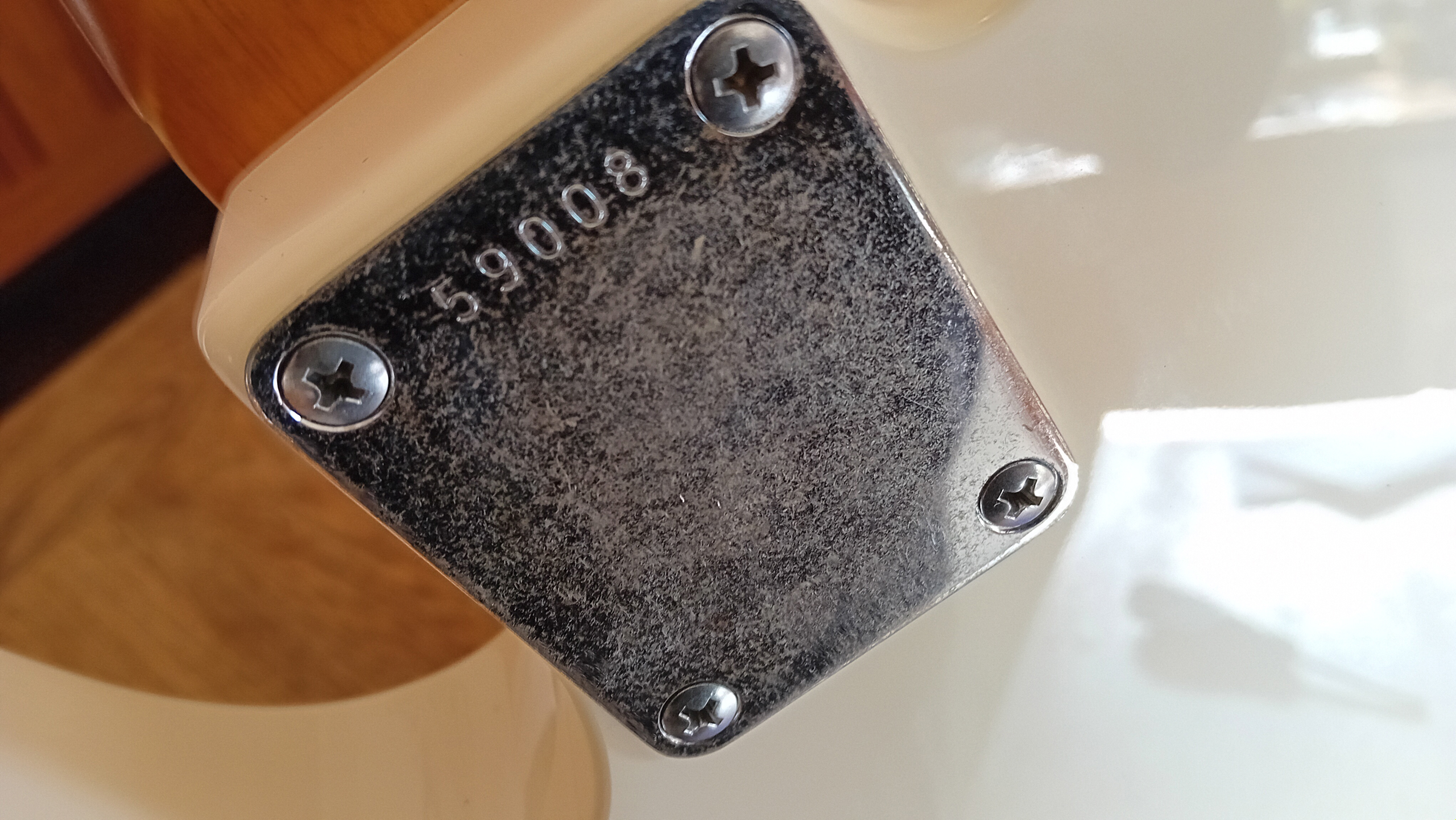
The neck fits nice and snugly into the neck pocket – and is attached with an AllParts, (Gotoh), pre-reliced and serial-stamped neck plate. (AllParts parts number: AP-0601-007). The random serial number is consistent here with the apparent late 50’s / early 60’s date of Strummer’s original Esquire, and the metal has a lightly-reliced patina – which I’m particularly keen to contrast, as a feature, against the pristine white paintwork of the new guitar body. The neck bolts are tightened evenly across the plate to avoid distortion. I tend to tighten just to “pinch” tightness – no more. Any additional “over-tightness” risks compressing the plate into the paintwork – splitting and damaging the finish, together with the wood below.

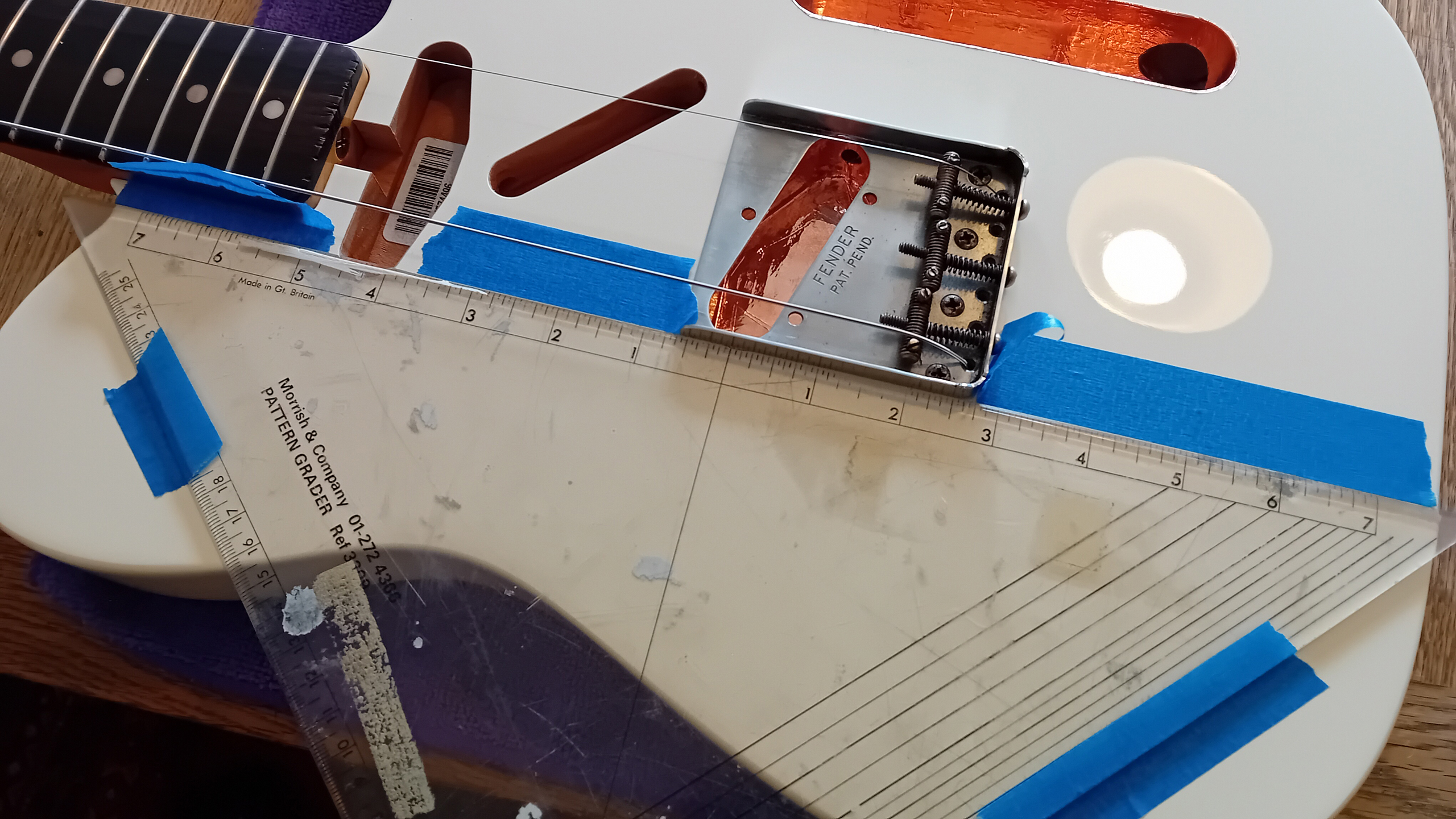
Continuing the “lightly reliced” metal against clean white lines theme… the bridge unit is a Fender “Road Worn” vintage type “ashtray” “Kan Ban” plate – with threaded “vintage” saddles. (Fender parts number 005-4162-049). I use a couple of spare guitar strings, and install them through the outer ferrules – so that the bridge is loosely captured, with the strings running along the outer “E” positions. Once the strings have been properly attached to the tuner pegs at the other end of the neck – they are lightly tensioned, and that provides sight lines which help ensure that the bridge and neck are installed in alignment. This type of vintage style bridge is attached to the body with four, (reliced), screws. (The body holes are pre-drilled, and the lacquer has already been neatly cut back around the countersinks. No need to prep the body further – although Fender do always recommend reaming out any overspray lacquer which may have accumulated in the countersinks. This to prevent splits running out onto the exposed bodywork, as the screws are driven home).
With my particular method of grounding the bridge – one of the central screw holes also has the grounding wire running down inside it. I always leave that particular screw until last. With the bridge correctly positioned and screwed down securely with the other three screws – this final screw can then be driven home with much less of a risk that the wire might cause it to deflect slightly, (and thus, potentially, nudging the bridge out of alignment).
If you’re installing a groundwire – you should also consider the gauge of the wire used, and how it may be pressed down into the lacquered surface by the bridge, as it’s tightened down. Hard glassy finishes may split – so plan any pressure points carefully in advance, and lay the ground wire so that potential splits can’t potentially run out onto open areas. (If in doubt – in can help to file a shallow relief channel to lessen the effect of the wire over the transition – but sandwiching it in-between pieces of copper foil – as I’ve done here – seems to be just as effective. At least, on polyester finished bodies… For nitro – you may have to be a little more exacting. In some cases – it may be adviseable to opt for a braided core, which can be teased out at the contact point).
The bridge screws need to be tightened down evenly across the body – and driven enough to draw the forward edge of the bridge down flat, against the face. There’s a tendency for the string tension to cause the front to lift slightly, at first – but once the screws are fully tightened down into their countersinks – the bridge is usually drawn flat and level.
At this stage – the positions of both the the neck and the bridge plate can still be adjusted, in relation to each other – in order to provide the correct alignment of the strings along the full length of the neck. It’s quite usual for a Fender neck to display a typically limited amount of side-to-side “slop” in positioning – whilst the factory drilled mounting holes for the bridge are usually drilled in the exact right place. Be prepared to slacken everything off a few times at both neck and bridge – and to reposition and check everything several times, until the exact, correct alignment is achieved. (There’s no absolute need to have the bridge pickup mounted at this stage – but if you do happen to have it to hand – installing it now will help reduce the number of times the bridge will subsequently have to be removed and replaced).
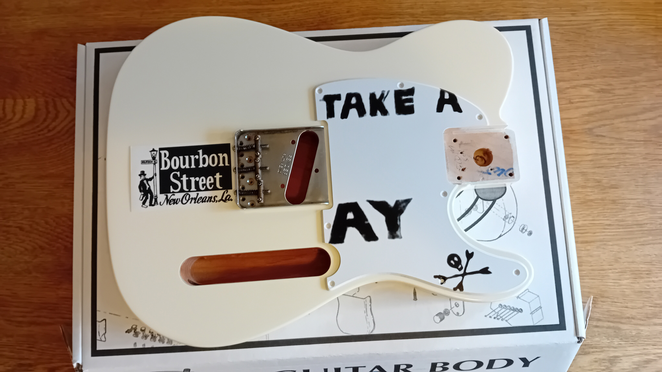
It isn’t usually typical to be concerned about decorative issues at this stage – but the correct placement and alignment of the bridge now allows for the definitive placing of two of the key graphic elements for the “Strummer” Esquire, (and I’ll need the top stripe to be in place, so that the pickguard can be installed on top of it). The signature black stripe runs along the top side of the bridge plate, with a “Bourbon Street” sticker placed centrally – right behind the bridge, on the flat of the body. With the body still relatively clean and “box fresh” – now is a good time to install both of the self-adhesive graphic elements.
I use a straight edge to define the line of the edge of the bridge unit. This has a bevelled edge – so I can get right under the folded edge of the metal plate. I then use some ordinary masking tape to mark a temporary line which I can then follow and sight against, to install the feature strip.
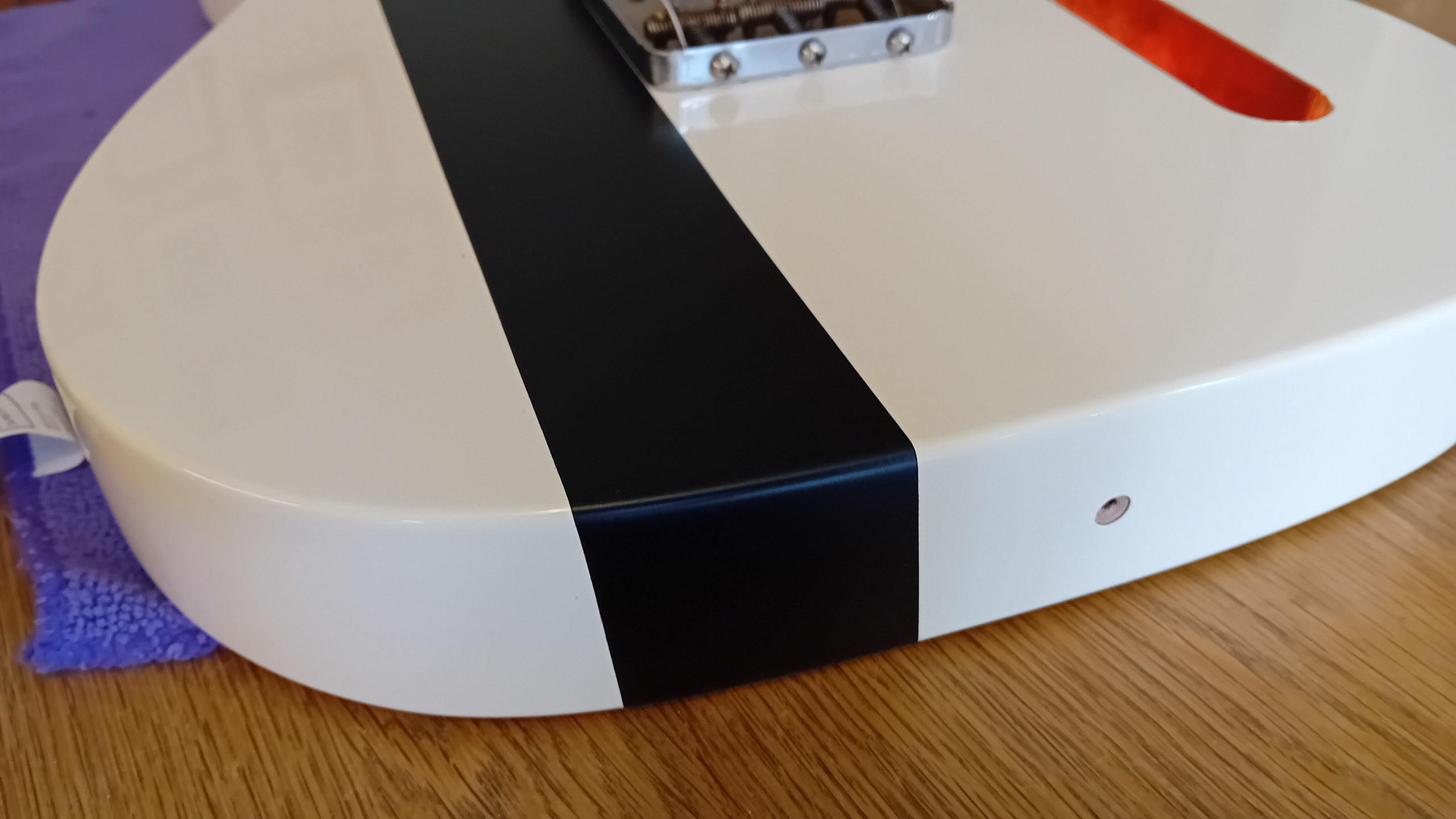
I’m using 50mm (2 inch) matt black vinyl tape. I’m pretty sure Strummer used textured “Gaffa” tape – but this 3M tape gives a much neater edge, and it won’t fray like Gaffa inevitably will, (revealing stray fibres and left-over gobs of soft, sticky goop. Gaffa’s got it’s uses – but it’s not exactly made for precision). The vinyl tape takes a few attempts to get just right – but once it’s heading in the right direction – it can be pressed down into place. A felt covered decal “squeegee” applicator is used to ensure that there are no bubbles left trapped under the surface, and that there are no rub marks left behind on the tape. The end result looks sharp, like a paint stripe – and the quality of the line will work well with the sharpness of the, plain black and white, “Bourbon Street” decal. However – before any tape or stickers are applied at all – the surface of the body needs to be properly cleaned down with naphtha and a soft cloth. Any dust or residue will potentially result in either incorrect adhesion, or raised faults showing under the applied tape.
If you can – it always helps to work into a good light source, when applying the tape. It helps to pick up any tiny defects, as things are thrown into shadow. Check that the edges of the tape roll aren’t dented or crushed at all – and try to work with a length which gives just enough spare at both ends. (The tape will be applied over the face and down each side – not across the back). Care also needs to be taken to keep the tape taught, around the changes of angle at the top edge – laying the tape straight, but without pulling the line too tight – thus stretching and distorting the shape. Because of the line of the top edge – the tape does, inevitably, go off-square slightly, as it goes down each side of the guitar – but it’s important to let the tape define it’s own path. The main thing is to ensure that there are no air bubbles trapped anywhere. The tape is finally trimmed off, in-line with the lower edge. This is achieved, easily enough by following the line of the body with a sharp pair of scissors, and making the cut in one stroke – rather than nibbling at it, or sawing-away with the scissor action.
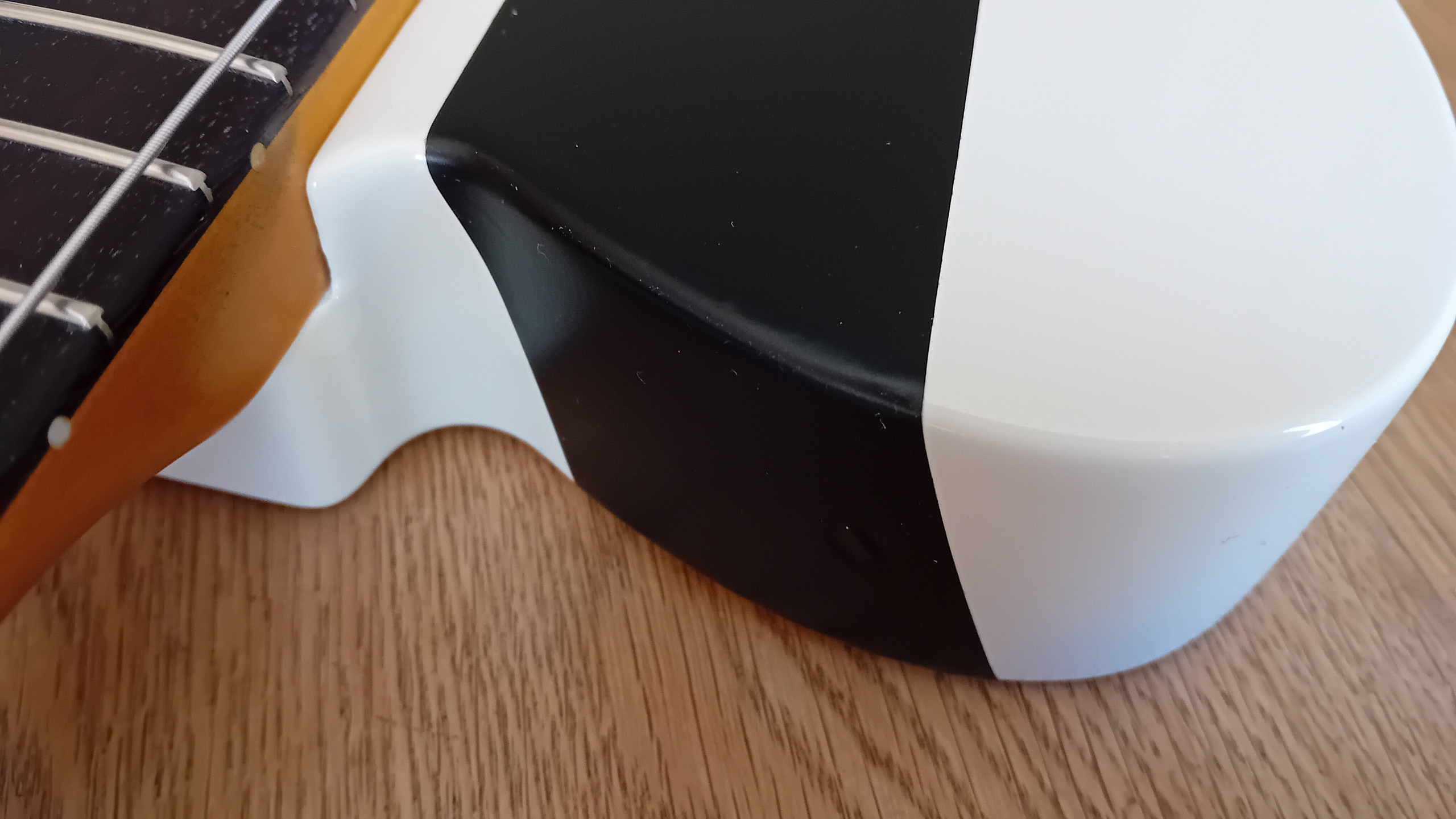
The forward edge is the hardest to get right – (hence repeated practice attempts, and working things out at the other end first, as rehearsal). At the upper bout – there’s a slight “S” curve to deal with along the edge, and this kicks the line of the tape out at quite an angle. I found it was best to concentrate on the top edge first, and then to work a line down the centre of the tape – pushing out and smoothing to the sides – gradually working all the way down and across, to the line of the bottom edge. Trimming with the scissors is a little trickier here – but practice and persistence pays off. Good job this 3M tape is available in 50 metre rolls! – I eventually get things right at the fifth attempt.
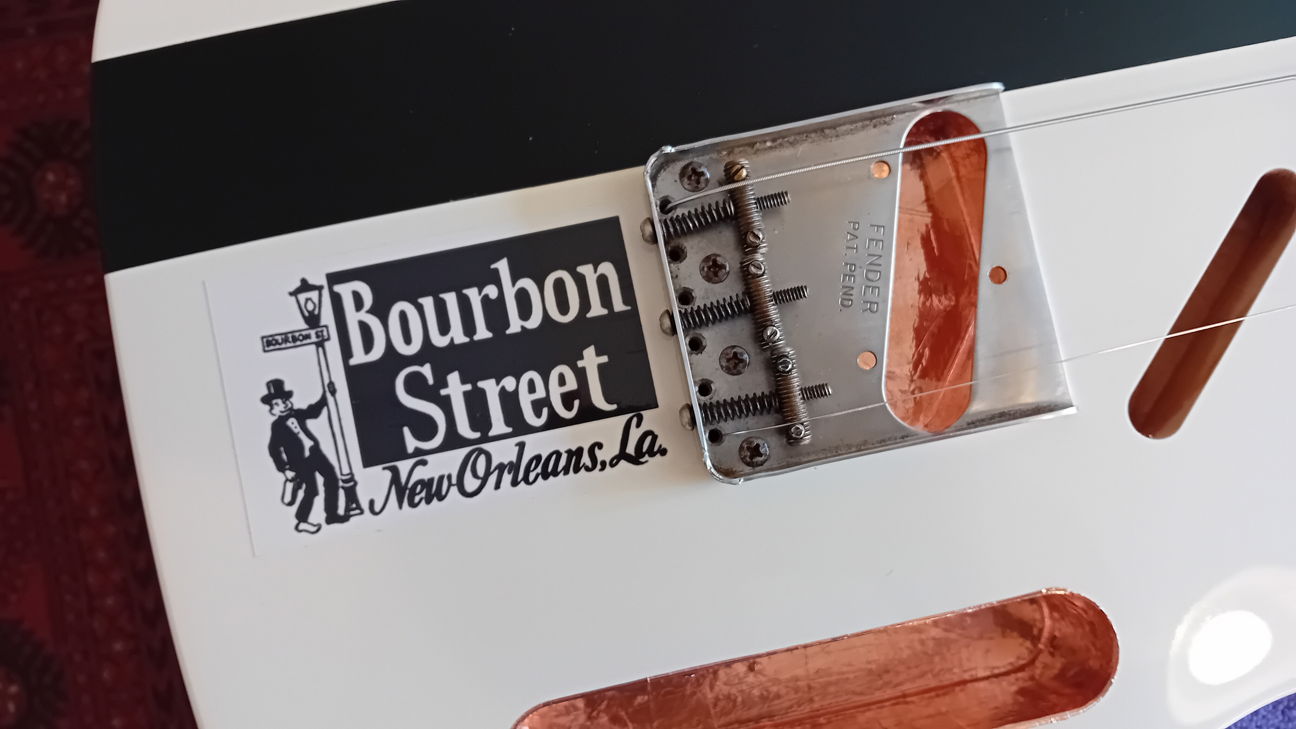
The “Bourbon Street” sticker – (this one is a good quality replica by AxeTreme Custom Shop) – is affixed right behind the bridge unit. The one on Joe’s original seems to be placed so that it just creeps under the bridge plate – rather than centering between it, and the edge of the body. I do the same here – using the combined lines of the bridge plate, and the new top stripe – to get the aligment just right. Once again – a clean and dust free substrate, and the elimination of all air bubbles with the help of a decal squeegee – are key.
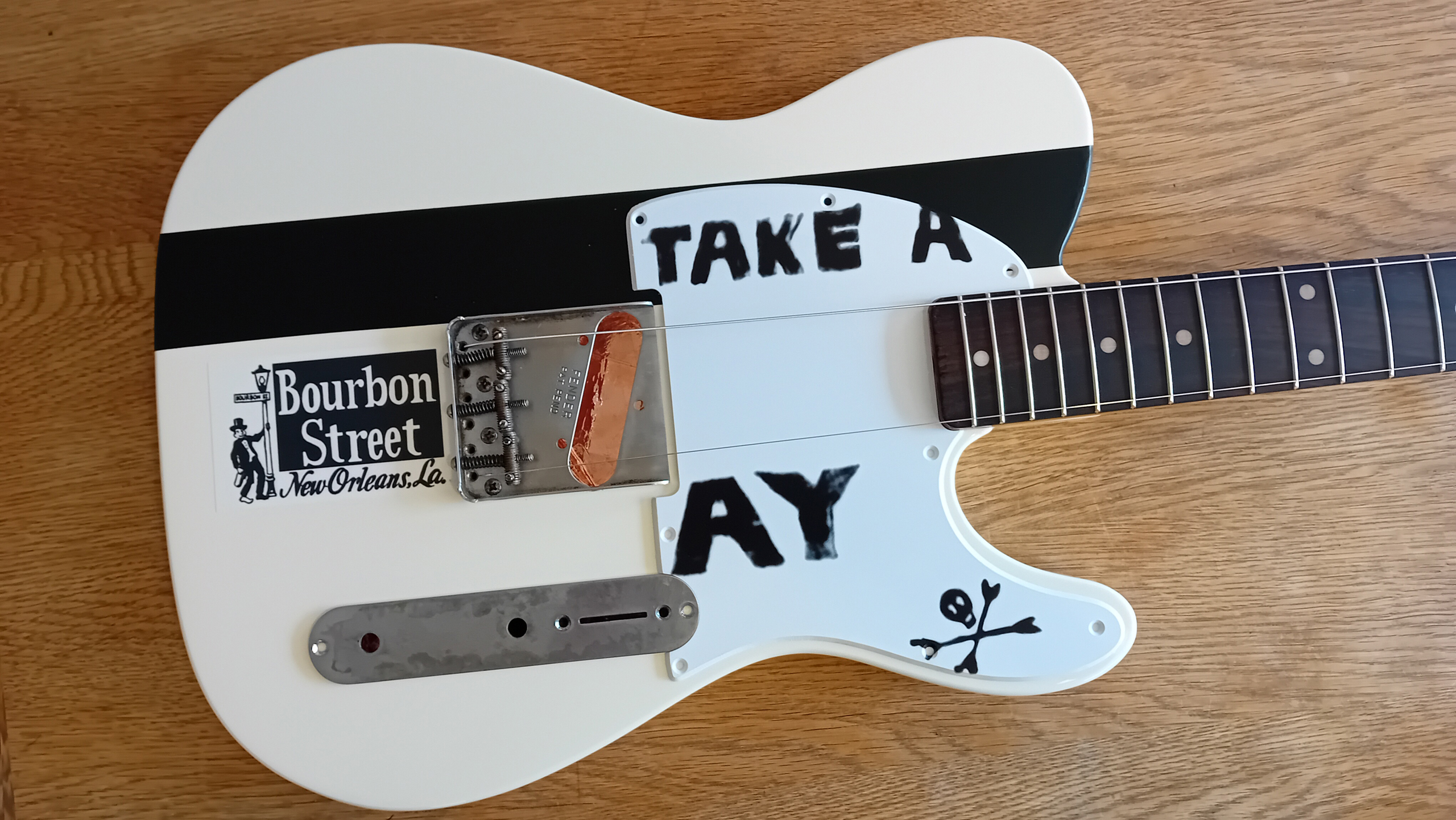
And finally – I can take a look at how things are developing. I already have the scratchplate and control plate to hand – so I can lay things out temporarily, and begin to see everything in context. It’s such a surprisingly simple yet effective design – and although the decals look as if they’re painted on – the whole thing could, potentially, be returned to plain white “vanilla” again, by simply removing the applied elements and reverting to a single ply white pickguard. (I could also opt to shield the neck pickup rout, and swap the pickguard out for a Telecaster version to accommodate an additional neck pickup. The Telecaster and Esquire geometry is otherwise identical).
In part two – I’ll move on to complete the hardware installation…
