


Before I attach the neck – I need to do a quick bit of work on the body. It’s a brand new, Fender MIM Jazz Bass replacement body – finished in black gloss polyurethane. (Fender parts number: 099-8008-706). It’s got the “modern” control rout – with a fat neck pickup opening, and a slightly shelved section over where it runs into the main control cavity. I’m not by any means convinced that I’ll actually be fitting ashtray covers to this bass – but I might as well cater for that potential, extra flexibility now – in case I’m ever minded in the future. I carve a suitable, flat, triangular fillet from obeche wood – and glue it into the outer elbow of the routed cavity with Gorilla PVA wood glue. While I’ve got the glue out – I thin some extra with a little water, and brush it sparingly over the entire inner surface of the rout. Whatever Fender uses in the factory, (some kind of shielding paint, perhaps?), doesn’t accept self-adhesive copper foil too well. The wood glue will provide a much better key, once it’s fully dry. Since all of my builds now get the copper foil shielding treatment – I want to make sure that the foil will stick…

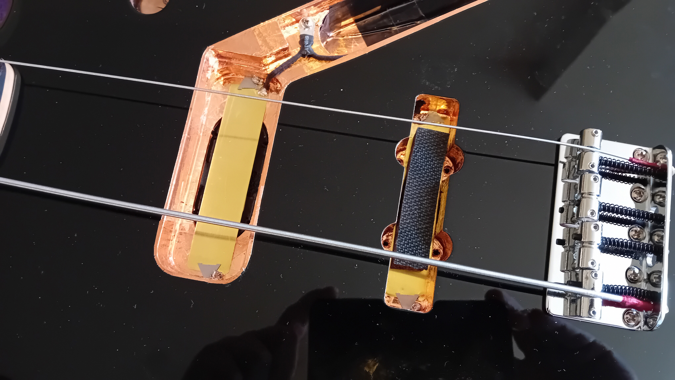
Once the glue is fully dry – I begin to line the main routs with copper foil. As the foil is laid – I can use it to help secure a bridge grounding wire, which runs all the way from the opening under the bridge, to my chosen location for a central “star” grounding point – on the “shelf” just behind the new fillet piece. The wire is simply the bare, twisted inner core, which has been stripped from a length of cloth-covered “push-back” wire. At the bridge end – the wire runs between two pieces of copper poil, which effectively “sandwiches” the wire between – lightly securing it to the body, as it does so, at the point where it emerges from the through-body conduit. (The end of the wire is pushed down the second bridge screw hole, where it will be secured, and make a good contact with the metal mass of the bridge). The rest of the wire is then run through the inter-linking conduit, and across the base of the main control rout. Additional pieces of copper foil help keep it in place – and as it gradually becomes buried beneath – contact with the foil ensures that the wire is secure, as the continuous grounding contact is spread throughout. At the “star” ground point – the other end of the wire is secured with a screw lug. Once all of the copper foil is laid – continuity can be demonstrated and checked with a multimeter.
It’s important that all of the copper shielding foil is somehow connected back to ground. Sometimes – there’s a need to directly link separate routs in the body, with additional inter-connecting wires. On the Jazz Bass for example – a connection is required between the main control rout, and the separate, bridge pickup cavity. However – I’ll be providing a pair of brass shielding plates under both of the pickups, later. Since they will be in direct, (metal to metal, conductive), contact with the copper lining foil – the continuity required will be achieved by simply connecting these additional shielding plates back to the main “star ground point.
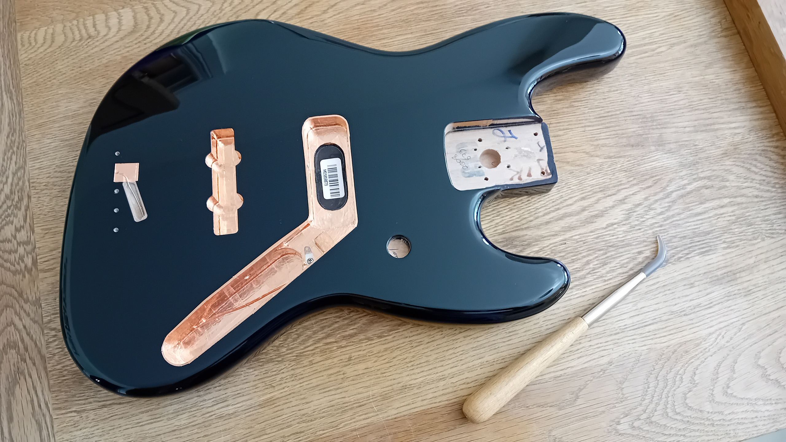
Eventually – the two pickup cavites are fully lined with copper. At the main rout – the foil is laid to slightly “lip” the cavity – with a couple of millimetres applied over the edge, and onto the front face of the body. For the bridge pickup cavity however – coverage is restricted to just below the lip. (The way the pickup cover emerges here would make any foil on the surface all too visible). The only place where the coverage isn’t completed – is where the in-factory body code sticker has been applied, directly under the neck pickup position. Since I’m fitting those extra, under pickup shield plates – the foil isn’t really required here, and I can therefore keep the “provenance” of the Fender body exposed, for any who want to search it out.
The copper foil is finally burnished down with an agate “dog tooth” tool. The adhesive on the copper foil is conductive – so burnishing not only helps the foil stick to the wood of the body better. It also helps the foil stick to itself better.

I’ve managed to source a (barely used), Fender bass bridge from another Standard Jazz bass. This one has black saddle intonation screws – so probably even came from a similar black bass originally. The bridge is anchored with five new screws, (Fender parts number: 002-1422-049) – with the outer pair locating the bridge first, and central screw following. Of the remaining two screws – the one with the grounding wire is left to last. That way – the wire can’t cause the screw to deflect the alignment of the bridge plate at all. All screws are fully tightened down – until the front edge of the plate is pulled down flat against the body.
At the bridge pickup – a spare cover is temporarily fitted, using four small springs underneath the attachment screws to push the cover up. (The type that are often used with Telecaster bridge pickups, work well). To position the cover – it’s shimmed away from the surrounding edges equally, with pieces of thin card – so that it’s sits centrally within it’s opening. After the positions of the four screws have been marked through with a sharp awl – four bass pickup attachment screws, (Fender parts number: 002-7035-049) are used to anchor the cover in place, with the springs pushing the cover upwards, under the strings.
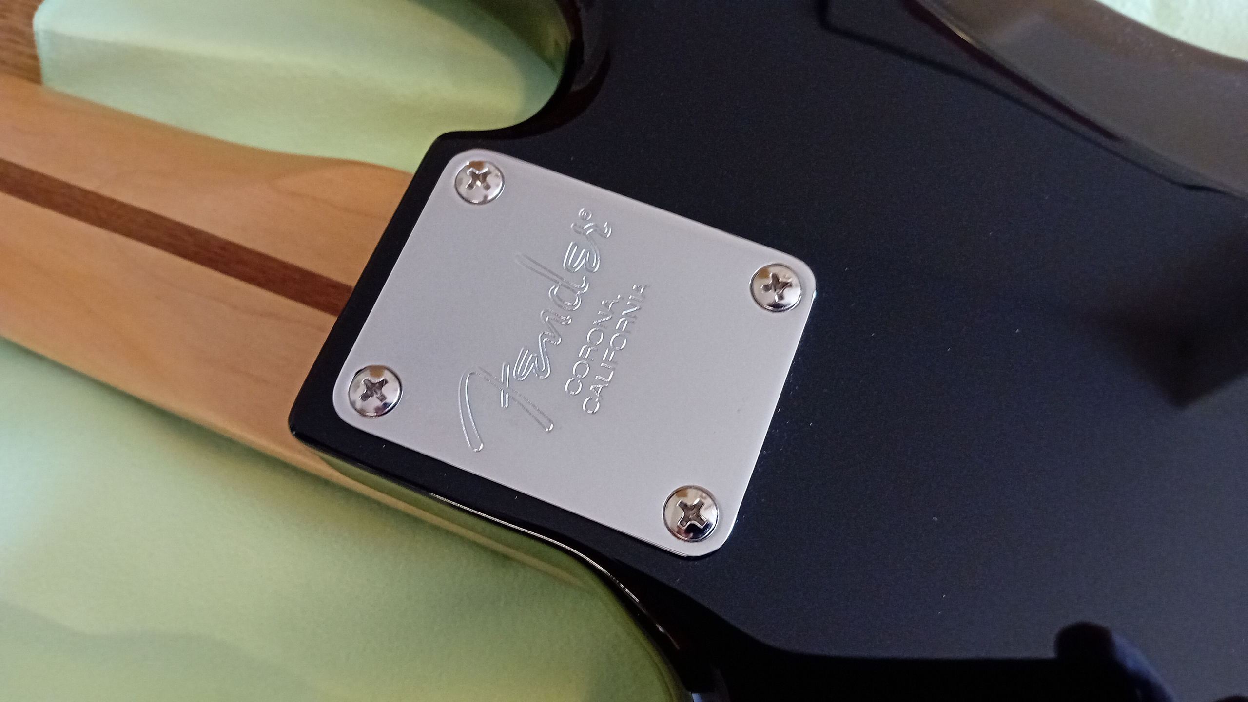
Now, at last, the neck can be attached to the body. The neck has already been drilled for a standard Fender fitting, and the existing, pre-drilled holes match up well with those on the body – so all I need to do is supply a suitable neck plate, and then fix the neck into the pocket with the usual, four steel bolts. I’m using a Fender “American Standard” “Corona” plate, (Fender parts number: 099-1445-100). The neck bolts are gradually tightened down, (but not overtightened!), evenly across the plate.
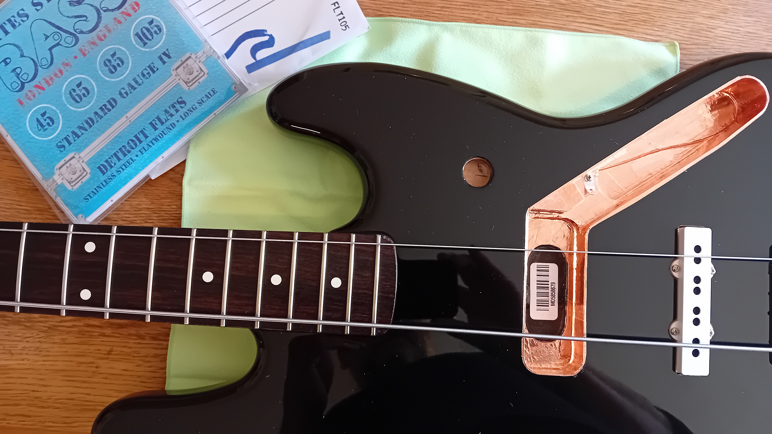
I had originally intended to use roundwound strings on this Jazz bass – but after fitting flatwounds on a couple of previous bass builds – I think I prefer both the sound and playability of flats. I always used roundwounds on my Precision basses previously – but since I used to have to adjust the tone/EQ to reduce any “clanking” sound from the strings occasionally hitting the frets, (and since the Jazz bridge pickup would seem to be specifically positioned to only accentuate similar frequencies) – I figure I’ll stick to flats again, as on my previous, “Vintage spec.” Jazz Bass build. These “Detroit Flats” (Bass Centre Elites) are great for the price, and since I like the weight of the standard gauge – I’ll use a set of 45-105’s here too.
The bass is strung with the outer two strings only, at first – tightening each, until the strings just straighten out. (No need to wind things up too much at this stage). I can then check the alignment of the strings along the entire length of the neck, and over the bridge pickup. If any adjustment is required – the neck plate bolts are lightly backed off, and the neck simply “shoved” into proper position – before re-tightening the bolts once more. (Patent “Fender neck slop” reduction method – 101). As it is – the neck seems to sit well enough, without any further adjustment required. (My… That dark, almost vintage rosewood looks great against the piano black body…)
From here on in – mounting the rest of the hardware – the procedure pretty much follows that of my recent, “Vintage spec” Jazz Bass, with a few specific, additional notes…

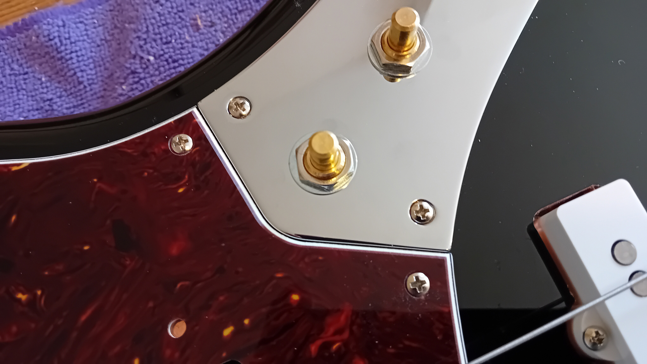
…Strap buttons first… These are Fender “Original” buttons, (vintage style) – and they’re mounted with white felt washers, to contrast, and help protect the finish underneath. (The pilot holes are pre-drilled on the replacement Fender Jazz Bass bodies – so you just need to lightly re-tap the holes, to clear out any PU finish that’s got down in there – before screwing-on the new buttons). To help keep the screws from backing-out over time – I sometimes glue a plug of wood into the hole, before tapping-in the new screw. (An old matchstick – trimmed to length – works well enough. This gives the screw threads something to bite against). I’m fresh out of straplocks – but I’ll add a pair of rubber, “Grolsch-style” blocks when I get hold of another batch…

Next – the control plate is fitted with it’s pots and jack socket. Three, CTS 250k, audio pots and a PureTone mono jack socket… The pots have lock washers underneath, and all four components have dress washers between the securing nuts, and the face of the chrome plate. Everything is tightened up by hand, with a socket wrench bit. (I use a short extention bar rather than the full wrench assembly – to avoid over-tightening, and potentially damaging the threads).

With the main control plate populated – I can then check the positioning of the scratchplate, neck pickup cover and control plate – allowing for the bodies of the control pots, within the main control cavity. Once the positions are right – the four pickup screw positions are marked on the base of the pickup rout with a sharp awl – using the holes on the cover as a simple, positional guide.
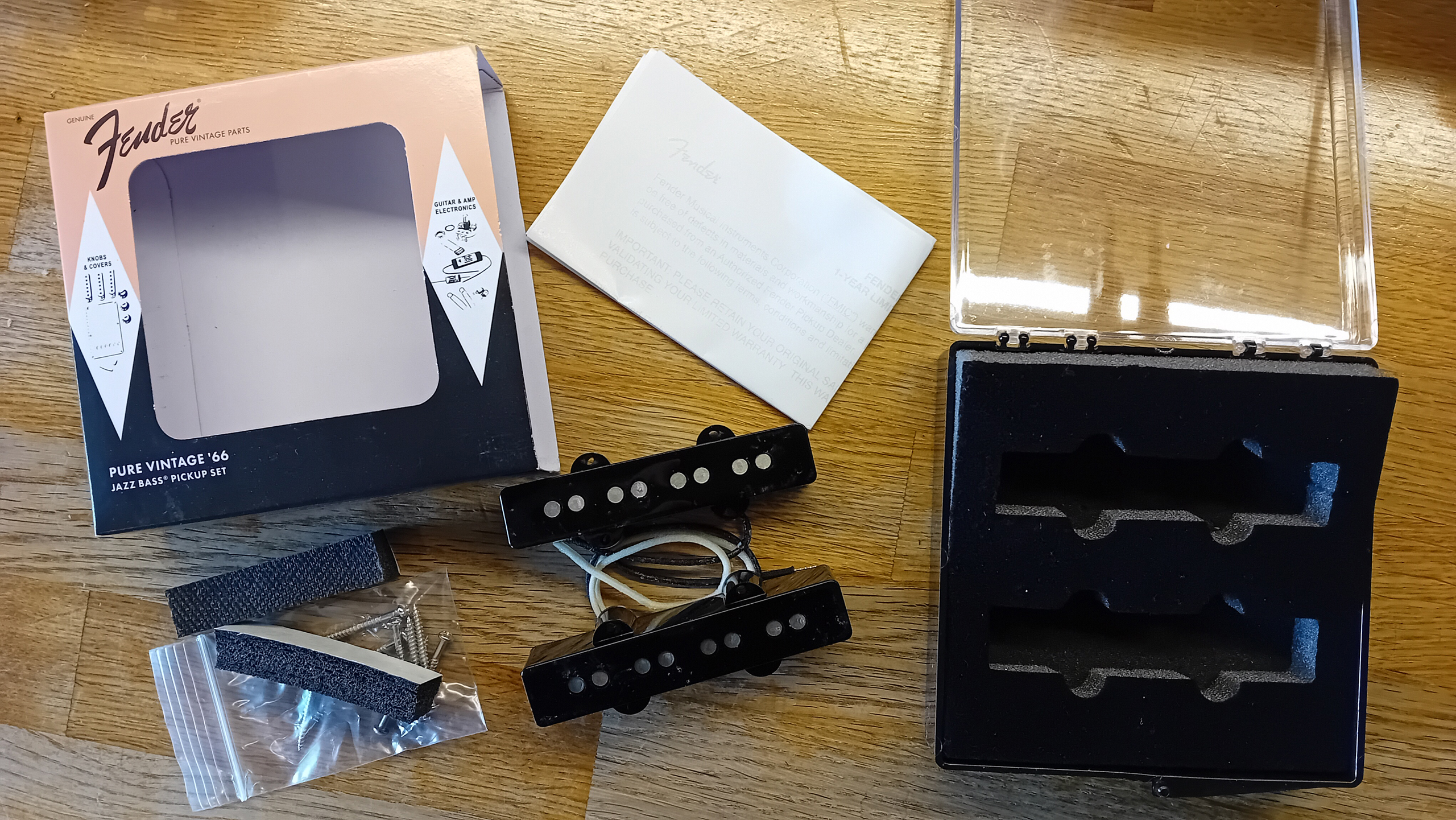
I’m using a new set of Fender “American (Pure) Vintage ’66” pickups for the build – and the set comes complete with everything I need to mount then to the body. However – there are no under-pickup, brass shielding plates supplied… I’ll have to make my own again.
Another DIY pair of shielding plates are cut out of 0.25mm thick brass sheet, using a pair of tin snips. 190 x 19mm for the bridge pickup plate, and 198 x 19mm for the neck. All edges are de-burred – with the sharp corners rounded off. They’re positioned on the bottom of the pickup routs, (the neck pickup plate needs a couple of card shims underneath, in the middle – where it bridges the shallow central recess) – and are held in position with triangular glazing brads and solder. Ground wires are attached to the corner of each plate – the wires then running-through and joining at a screw lug, at the central “star” grounding point. (Continuity is checked throughout, as usual, with a multimeter). Finally – the two, Fender supplied, neoprene rubber “springs” are attached centrally, to the shielding plates, using their self-adhesive strips.

The pickups are then mounted using the screws provided – (except I’m replacing the stock black covers, with a pair of white, generic, aftermarket replacements). Once installed – the pickups are tightened down to their approximate “working” heights, under the strings – and the pickup leads routed through into the main control conduit, (where they’re coiled up, out of the way, until the tone circuit is built).

The scratchplate and main control plate are then placed back, in position, on the body. Once everything is in the right place – and the join between the plates is closed, (and as tight as possible) – the plates are taped down to keep then from moving, whilst the first attachment screw holes are tapped. (The Fender scratchplate comes with a bevelled edge at the interface with the metal control plate – so the plates can’t “butt together” as tightly as you might wish. The position and size of the upper volume control pot also means that the pot housing tends to push right up against the upper edge of the main control rout. The joint between the plates is therefore made as tight as possible – whilst still evenly revealing the white bevel on the scratchplate, below).
Because the interface between the plates is such a “critical” visual detail – I found it much easier, in this case, to deal with the screws in that vicinity first. That way – the plates could be secured firmly to the body, in the exact place they needed to be – and the remaining holes tapped wherever they subsequently fell. Each hole is marked, countersunk, drilled and tapped – with a set of oval head, countersunk chrome Fender scratchplate screws used throughout.
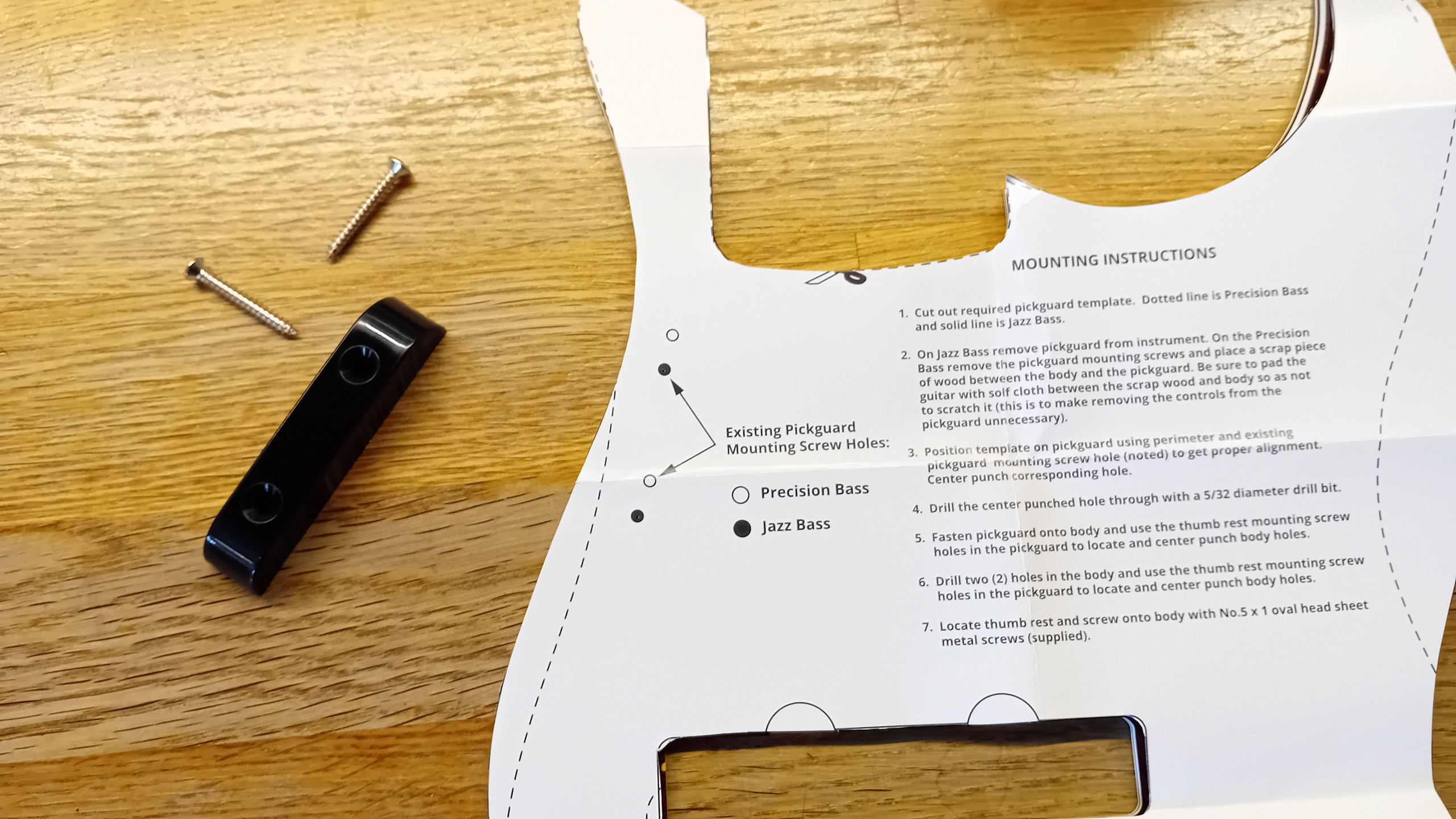
Once all of the holes have been drilled – it’s useful to take the plate off again, to check that all of the countersinks have been neatly cut – and that none of the screws risk splitting the finish around. (…And to brush away any loose debris). It’s also the ideal opportunity to drill the scratchplate for a pull-bar. Fender supply a cut-out paper template for the, later favoured, (above string), mount option. Once marked through onto the plate – the holes can be drilled out. (Drill through from the front of the plate, with a sharp, clean HSS drill bit. But use a backing block – to prevent the bit from “tearing-out” on the back of the plate).
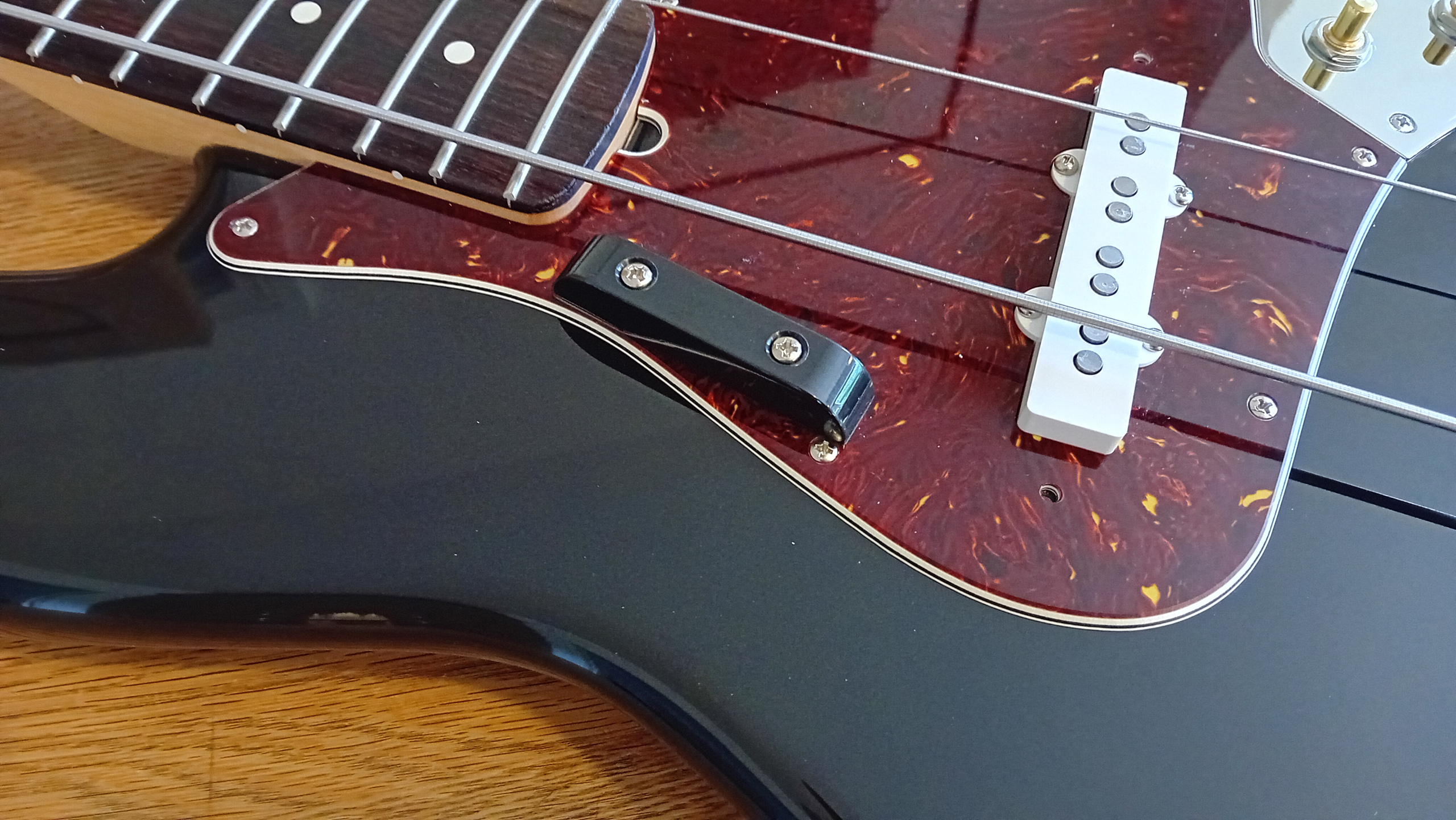
The scratchplate can then be re-mounted to the body, and the pull-bar screw hole positions marked, and drilled through, onto the body itself. (Countersink too, if you wish, to prevent any possibility of the finish splitting). The pull bar can then be firmly attached to the bass, using the two screws provided.

Finally – the remaining (middle) strings from the retained set are attached, and the bass set to a more positive string tension. (Still not full tension – but closer to proper tune – in order to roughly assess the neck bow, and action. The proper “tuned” tension will be dialled-in during the setup process, to follow).
